![[Company Logo Image]](../images/colosseum.png)
Colosseum Builders—Volume 3 of The
Structure of the Iowa Class Battleships
Books
Source Code
Hopefully, volume 3 will be completed by the end of 2024. We cannot guarantee what will be in the final book but here are some previews of what is likely. Once again, this book has gone to the original plans and will contradict much of what is in print.
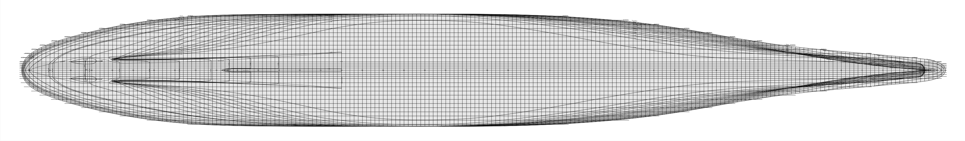
The hull structure from the original tabular mold loft data. The tabular data might even make into this book. Hopefully some manufacturer will finally create an Iowa-class kit with a hull form that is close to correct.
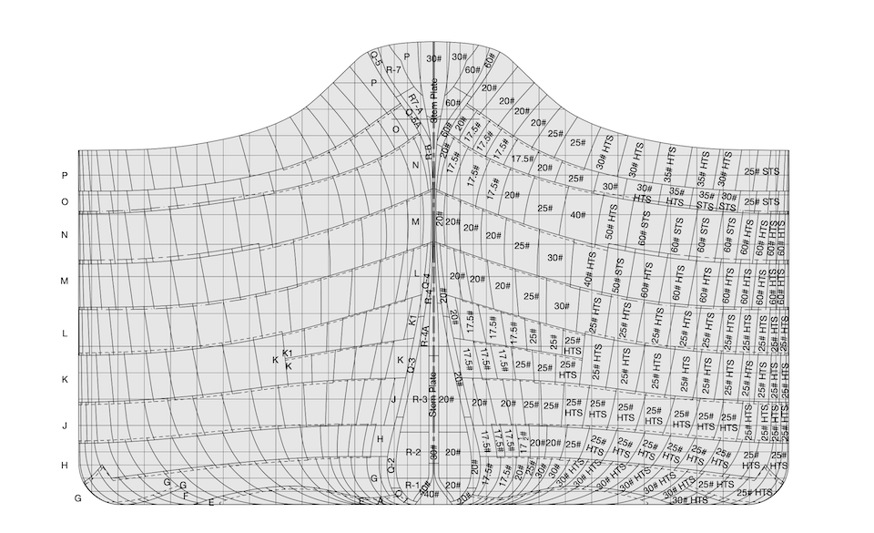
All of the plates and joints of the hull shell have been mapped out. So have the locations of sea chests.
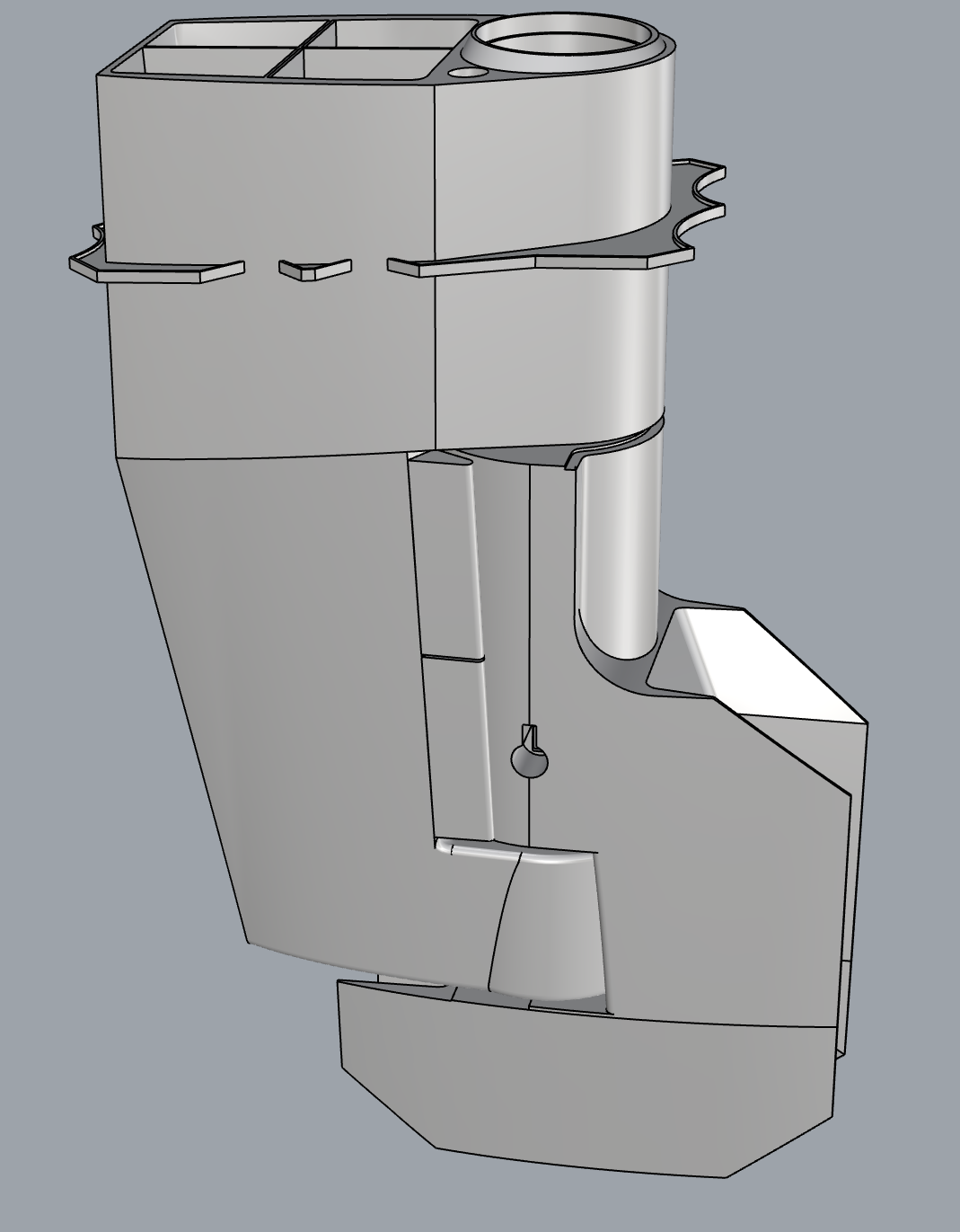
Structural details, such as the rudder supports.
What do model kits get wrong?
Model kits tend to get the bow, and especially the stern,
way off. The Iowa-class battleships have a bulbous bow.
Unlike modern ships with a bulbous bow, the Iowa-class
have a knife edge extension above the bulb.
Sterns tend to have several errors. The first among them
is that they tend to depict the Iowa-class as having skegs.
Many books also refer to the extensions housing the
inboard propellers as skeg. Yet the Iowa-class battleships
do not have skegs. None of the plan for the Iowa-class use
the term skeg. The actul plans call these
structures twin keels.
Skegs
Historically, skegs are a (1) center line (2) extension
from the keel that (3) mounts a rudder. The twin keels are
not on the center line. In modern usage, a vessel can have
skegs off the center line. However, the next issue is that
the twin keels are not extensions from the hull. They are
an integral part of the hull structure. Finally the twin
keels do not mount a rudder.
When a kit tries to represent the twin keels as
extensions to the hull, rather than an integral part of
the hull, the result is a misshapen hull form. The most
visible issue is the length of the outboard shafts outside
the hull.
Docking Keel
Kits tend to omit the docking keel that extends into the
tunnel between the twin keels. The docking keel supports
the weight of turret number three when the ship is in dry
dock.
Half Siding
Half siding is an area of the ship that extends
horizontally and linearly from the keel center line. Half
siding is either flat or it bends along the keel. The
Iowa-class have half siding from the bow to the stern. The
half siding descends at the bow, then it is flat for most
of the ships' length. Then it narrows and rises upwards in
the twin keel's tunnel. As it emerges from the tunnel, the
flat siding widens to create a mounting location for the
rudders. Moving it narrows and ends at the stern.
Kits tend to depict the area of the hull at the rudders as
being curved but lengthwise and crosswise.
Knuckles
The hull form has two knuckles towards the stern. The
upper knuckle is visible in photographs. The lower is
below the waterline. Amidship the hull cross section is
vertical. Aft of this vertical section, the hull form
divides into three areas separated by knuckles. The upper
two areas have a linear cross section forward. Moving aft,
the hull form starts to curve and eventually the three
areas return to a continuous curve at the stern.
Plating
Some kits have started to include seams between the
plating strakes. The problem is that these seams are only
visible above the waterline at the bow and stern where the
strakes lap. Elsewhere, where the strakes butt, you have
to get very close to the ship to pick the lines out. Even
where the plates lap, they are beveled and the
plates are about 1/2" thick. Even at a huge 1:96 scale, a
lap is only about 0.005", making it nearly invisible.
At least one kit depicts plating lines between plates
within strakes. Almost all of these joints are butted and
are hard to see up close on the ships. Even if the strake
divisions were visible in scale, the lines shown on kits
tend to be a work of fiction. Why go to all the trouble of
depicting strake divisions and then do it wrong?
Bilge Keel
The outer edge of the bilge keels on the Iowa-class
battleships do not form a continuous, second degree curve.
The natural curves of the bilge keels are truncated at the
side and bottom so they will not extend beyond the hull
form. This gives the outer edge a distinctive wave that is
clearly visible in photographs.